BLDC MACHINE
Information page
What is BLDC ?
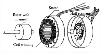
The construction of modern brushless motors is very similar to the permanent magnet synchronous motor. Figure 1 below illustrates the exploded view of the brushless DC motor. The stator windings are similar to those in a polyphase AC motor whereas the rotor encompasses the magnetic field structure. These type brushless DC motors can be operated as single phase, two phase or three phase. The main disadvantage of using single phase compared to three phase brushless DC motor is its inability of self-starting characteristics. However, for specific application such as the mechanical chopper, the single phase motor is the highly appropriate. The rotor is encloses one or more permanent magnets. The detection of rotor position (or magnetic poles) to produce signals to control the electronic switches of the BLDC distinguish itselves from the AC motors. The common electronics switch of MOSFET or IGBT are employed that energise the coil windings. The most common position/pole sensor is the Hall element, but some other applications optical sensors are also employed.
Figure 1: Exploded view of the brushless DC motor
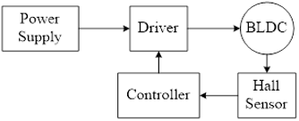
Figure 2(a) shows block diagram for energizing the coil using brushless DC motor configuration. BLDC operates in a closed loop control. Commutation logic circuit and switching electronics are used to convert rotor feedback position information that is detected by Hall Effect Sensor. Figure 2(b) shows the position of Hall Effect Sensor (HES) that detects the rotor pole placed based on the stator pole pitch, σst.
(a) block diagram (b) position of Hall Effect Sensor (HES)
Figure 2: Principle of BLDC
Figure 3 below shows switching sequence for brushless DC motor configuration. The driver for the brushless DC motor configuration generates switching signal with HES by detecting the poles and thereby energizing the coil winding current positive or negative direction accordingly. In brushless DC motor configuration, the speed of rotation can be controlled by increasing the input voltage to the coil winding. The increasing of input voltage increase the speed as more pole is being detected by the sensor.
Figure 3: Switching sequence
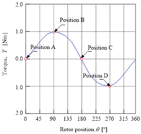
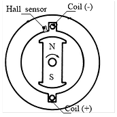
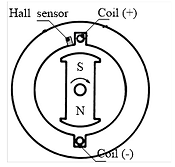
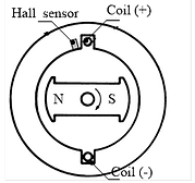
Figure 4 below shows the ideal torque characteristics of single phase brushless DC motor with two poles. There are four positions that being highlighted namely position A, position B, position C and position D. Based on the position at any point of operations, the basic principle operation of brushless DC motor is shown in Figure 5. Consider a permanent magnet pole N and S that is free to revolve about a particular axis. Assuming that the negative current direction produces N pole whereas the positive current direction produces S pole. At particular position A, initially there is zero coil current. As, the hall sensor detects the rotor pole and gives signal to switching circuit so that coil is being energized in negative current and positive current direction for another coil. Therefore, opposite pole is induced at both coil thus the rotor move away from the coil and move in clock wise direction. At position B, the rotor is at maximum distance of each pole thus, maximum torque is achieved. At the same time, the positive current direction for coil already induce S pole that makes the rotor pole (N) get attracted and moves to position C. At this particular position, the HES detects the S pole in the rotor thus, provides signal to switching circuit so that coil is being energized in positive current and negative current direction for another coil. At position D, the rotor is at maximum distance from each coil hence, maximum torque is achieved. Since the pole is in the opposite direction thus, negative torque is produced. Similar principle of operation for brushless DC motor is visualized when the rotor rotates from the other position.
Figure 4: Ideal torque characteristics
(a) Rotor Position A (b) Rotor Position B
(c) Rotor Position C (d) Rotor Position D
Figure 5: Basic principle operation of BLDC